


 English
  русский
  Français
  Indonesia
  عربى
عربى  中文简体
中文简体

Aluminum Radiator Cores: Tube-Fin vs Plate-Fin & Core Sizing Guide (2026)
Content
- 1 What Is an Aluminum Radiator Core?
- 2 Aluminum vs Copper Radiator Cores: Key Performance Metrics
- 3 Manufacturing Processes: CAB Brazing, Vacuum Brazing, and Mechanical Assembly
- 4 How to Select the Right Core Size and Tube Configuration
- 5 Tube-and-Fin vs Plate-and-Fin: Which Structure Suits Your Application?
- 6 Common Failure Modes and How to Prevent Them
- 7 Maintenance and Cleaning Tips for Aluminum Radiator Cores
- 8 Custom Aluminum Radiator Cores for Generators and Industrial Equipment
What Is an Aluminum Radiator Core?
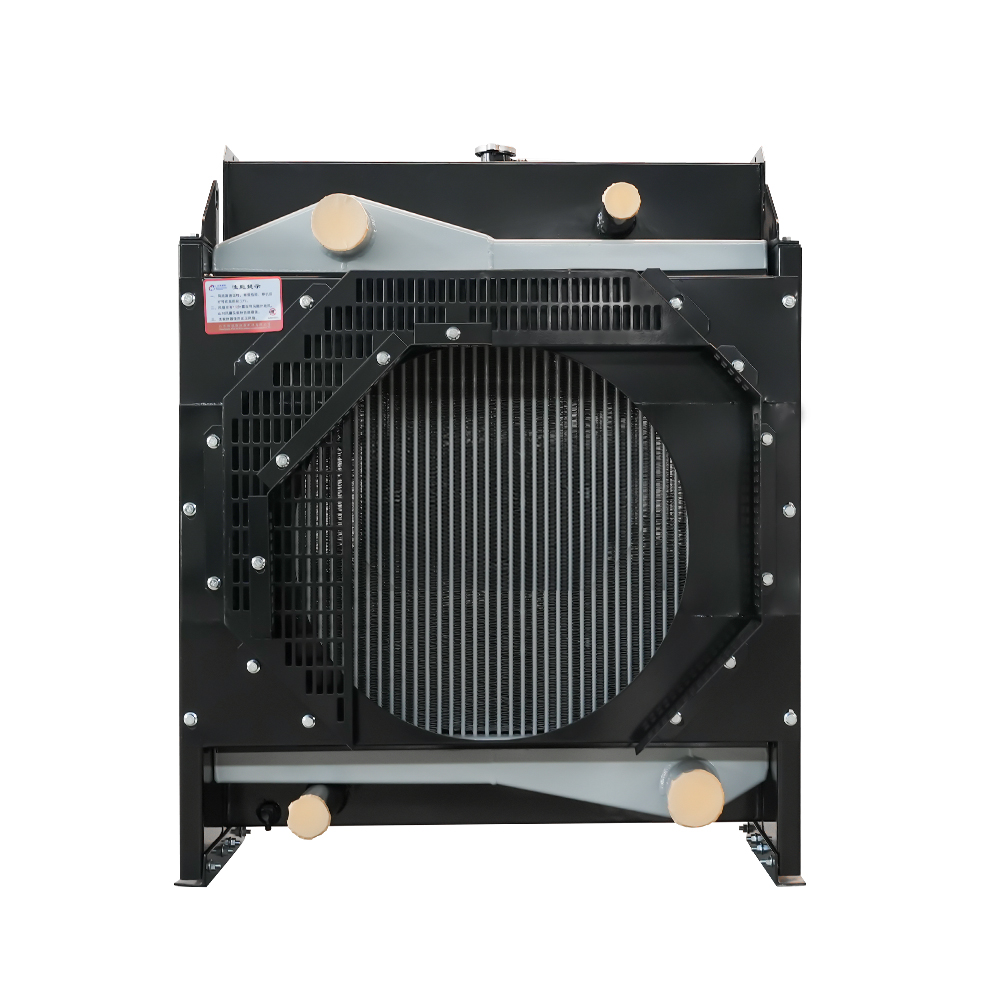
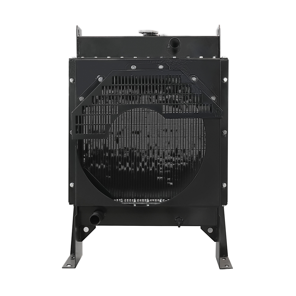
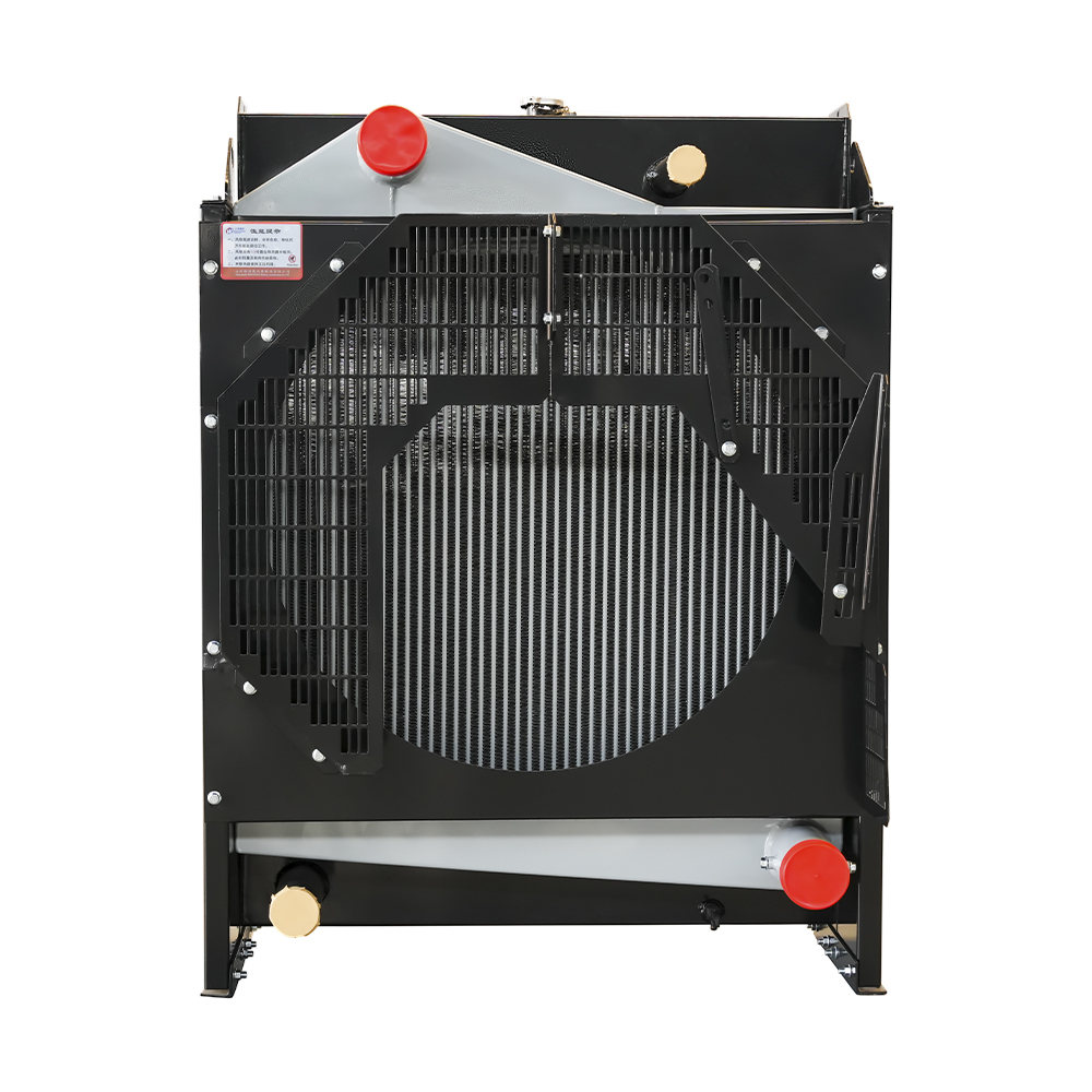
The core is the heat-exchange heart of any radiator. It sits between the end tanks and does the actual work of transferring heat from engine coolant to the air stream. In an aluminum radiator, the core consists of flat or round tubes, dense fins, header plates, and side supports — all joined without glue or epoxy.
Each component plays a specific role: coolant travels through the tubes, fins multiply the surface area for air contact, headers distribute flow evenly, and side plates provide structural rigidity. When you hear “all‑aluminum core,” it means the entire assembly — tubes, fins, headers — is brazed into one homogenous piece. This eliminates the dissimilar‑metal corrosion points that plague older copper‑soldered designs.
Aluminum vs Copper Radiator Cores: Key Performance Metrics
Many people assume copper cores are better because pure copper conducts heat nearly twice as fast as aluminum. The numbers back that up: copper’s thermal conductivity is about 400 W/m·K against aluminum’s 205 W/m·K. But a radiator is not a solid block of metal — it is an engineered assembly where total heat rejection depends far more on fin density, tube design, and air‑side efficiency than on raw metal conductivity.
Aluminum cores consistently win on weight and cost. The metal itself is about 40 % lighter per unit volume, and raw material prices run 30–50 % lower than copper. That means a fully brazed aluminum core can often be made larger or with tighter fin pitch — 18 to 22 fins per inch versus the 10–14 typical of copper‑brass units — without a weight penalty. The increased surface area closes the thermal performance gap and, in many applications, surpasses it.
| Property | Aluminum (Al) | Copper/Brass (Cu) |
|---|---|---|
| Thermal Conductivity | 205 W/m·K | 400 W/m·K |
| Density | 2.7 g/cm³ | 8.9 g/cm³ |
| Relative Weight (same volume) | ~40% lighter | Heavier baseline |
| Raw Material Cost (per kg) | $3–$4 | $8–$10 |
| Typical Service Life | 10–15 years | 12–15 years (if joints hold) |
Long‑term durability tells a similar story. Copper‑brass cores rely on solder joints that suffer from galvanic action when exposed to stray currents or mixed‑metal contact. An all‑aluminum brazed core, by contrast, forms a continuous metallurgical bond with no electro‑chemical penalty. That is why aluminum cores are the standard for modern diesel generators, industrial equipment, and performance vehicles — they deliver predictable heat rejection without corrosion‑related failures.
Manufacturing Processes: CAB Brazing, Vacuum Brazing, and Mechanical Assembly
How an aluminum core is joined determines its burst pressure, leak resistance, and fatigue life. Three methods dominate the market.
- Controlled Atmosphere Brazing (CAB) uses a nitrogen‑purged furnace with a flux that melts just below the aluminum filler. Every tube‑to‑fin and tube‑to‑header interface becomes a uniform braze joint. This process delivers excellent leak‑tightness and high‑volume consistency, making it the first choice for OE genset providers and heavy‑duty aftermarket cores.
- Vacuum Brazing eliminates flux entirely by pulling a high vacuum and using magnesium to clean oxide layers. It is ideal for extremely thin‑wall tubes or intricate multi‑pass geometries, but the batch‑furnace nature drives up cost. Vacuum‑brazed cores appear in aerospace‑grade or ultra‑compact industrial packs where the budget allows.
- Mechanical Assembly relies on gasketed or swaged joints. It is the least expensive path and works for low‑pressure, light‑duty applications. However, the mechanical seals degrade over thermal cycles, making this method unsuitable for continuous generator duty or high‑vibration environments.
| Process | Typical Application | Airtightness | Relative Cost |
|---|---|---|---|
| CAB Brazing | Industrial generators, automotive OE | Excellent | Moderate |
| Vacuum Brazing | Complex/small-batch designs, mission-critical cooling | Excellent | High |
| Mechanical Assembly | Light-duty aftermarket, low-stress installations | Good (gasket‑dependent) | Low |
How to Select the Right Core Size and Tube Configuration
Sizing a core starts with the engine’s heat rejection, not its mechanical power. A 100 kWe diesel generator typically dumps 120–150 kW of heat into the coolant, and the radiator must shed that heat under worst‑case ambient conditions. The required core frontal area (A) can be estimated from:
A (m²) = (Heat Rejection [kW] × 1.2) / (U [W/m²·K] × ΔT [K])
Where U is the overall heat transfer coefficient of the core — typically 80–120 W/m²·K for tube‑and‑fin and 120–180 W/m²·K for plate‑and‑fin — and ΔT is the difference between coolant inlet and ambient air temperature. A 15–20 % safety margin covers fouling and altitude derating.
Tube count, diameter, and row depth then fine‑tune the design. More rows increase thermal capacity but also raise air‑side pressure drop, which can starve the fan. A 2.25-inch-thick core with 2 rows of 1-inch tubes offers a pragmatic balance for most standby generators — it provides roughly 15 % more heat rejection than a 1.5‑inch core, at the cost of a 20–25 % increase in fan power draw.
| Generator Rating (kWe) | Approx. Heat Rejection (kW) | Typical Core Size (W×H×D mm) | Recommended Tube Configuration |
|---|---|---|---|
| 50 kWe | 60–75 kW | 600 × 500 × 60 | 2 rows, 1″ tubes |
| 100 kWe | 120–150 kW | 800 × 600 × 80 | 3 rows, 1″ tubes |
| 200 kWe | 240–300 kW | 1000 × 700 × 100 | 3 rows, 1.25″ tubes |
These dimensions assume 45 °C ambient air and a typical marine/industrial fan profile. Elevation above 1500 m, high‑dust environments, or enclosure‑mounted setups call for larger cores or wider fin pitch, which we address through custom engineering.
Tube-and-Fin vs Plate-and-Fin: Which Structure Suits Your Application?
The internal architecture of the core drives everything from heat rejection density to vibration survivability. Two structures dominate: tube‑and‑fin and plate‑and‑fin.
| Structure | Advantages | Disadvantages | Best Applications |
|---|---|---|---|
| Tube-and-Fin | Lower material cost, easier to repair, good heat transfer per mass | Lower burst pressure, fin-to-tube joints can fatigue under severe vibration | Automotive, rental generators, light industrial |
| Plate-and-Fin | Extremely rugged, high burst pressure, denser heat transfer area | Higher cost, more difficult to clean internally, heavier | Mining, marine, continuous-duty industrial gensets |
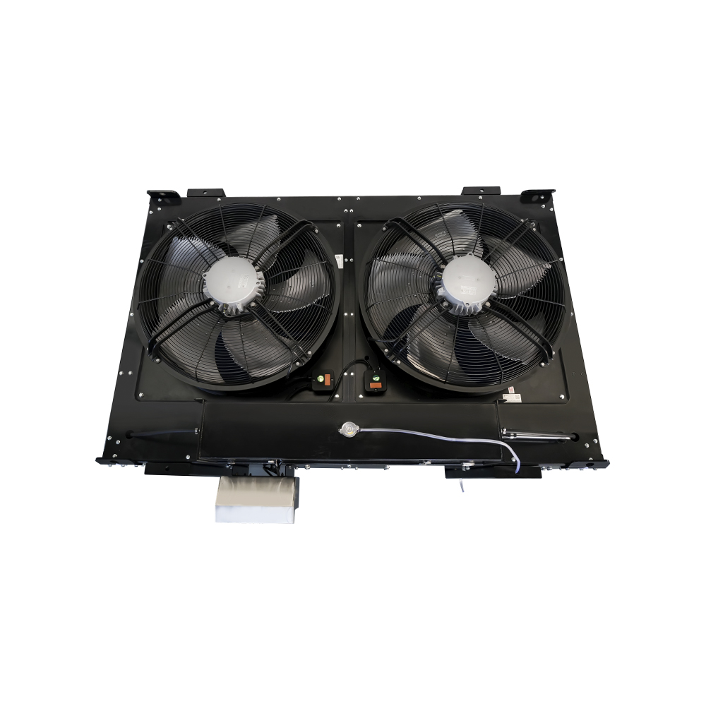
Tube‑and‑fin cores align well with budget‑sensitive or moderate‑stress applications. They can be manufactured quickly and still meet the cooling demands of many 50–100 kWe generators. In high‑vibration or high‑shock environments — vibratory pile drivers, offshore platforms, tracked mining equipment — plate‑and‑fin cores are the far safer bet. The stacked‑plate construction resists fatigue cracking that would otherwise propagate along the tube‑to‑header braze joint. For a deep dive into each type, you can explore our tube‑and‑fin generator radiator options and plate‑and‑fin generator radiator designs.
Common Failure Modes and How to Prevent Them
Even the best aluminum core can fail if the operating conditions exceed its design limits. Three failure modes account for the majority of premature core replacements.
- Weld (braze) cracks: Cyclic thermal expansion stresses the tube‑to‑header joint. Low‑quality brazing or insufficient flux leads to micro‑cracks that grow into leaks. Prevention starts with specifying CAB or vacuum brazing. Maintenance: perform a pressure test at 2000‑hour intervals, looking for any drop above 2 psi over 10 minutes.
- Fin collapse: High‑pressure washer wands or road debris can flatten fins, blocking airflow. Use a wide‑fin‑pitch core (3.0 mm or more) in dusty environments and always clean with a low‑pressure fan‑directed spray. A collapsed fin section increases fan power draw and can raise coolant outlet temperature by 8–12 °C.
- Galvanic corrosion: When aluminum touches a copper pipe or a steel bracket without isolation, an electrolytic cell forms. The aluminum acts as the anode and corrodes. Prevent this with isolating rubber mounts, dielectric unions, or conformal coatings on the core exterior. Inspect for white powdery deposits at attachment points every 1000 hours.
Maintenance and Cleaning Tips for Aluminum Radiator Cores
Preventive maintenance directly extends core life by keeping fin passages open and catching small leaks before they escalate. The following intervals, based on industrial generator operating data, form a practical baseline:
- Every 500 hours or monthly: Visually check fin surfaces for debris, insect nests, or bent fins. Remove loose debris with a soft brush or low‑volume vacuum.
- Every 1000 hours: Blow out the core with compressed air (max 60 psi) from the fan side outward, or flush with a garden hose at low pressure. Avoid directing a pressure‑washer nozzle at the fins — it can fold them over and cut cooling efficiency by 25 %.
- Every 2000 hours: Inspect braze joints around the header plates and mounting flanges for hairline cracks. A dye‑penetrant test is quick and reliable on bare aluminum.
- After any salt‑water exposure: Rinse thoroughly with fresh water and apply a light‑duty aluminum‑safe corrosion inhibitor spray to the outer surfaces.
Custom Aluminum Radiator Cores for Generators and Industrial Equipment
Standard catalog cores fit many applications, but when the installation space is tight, the ambient conditions are extreme, or the cooling load is non‑standard, customization is the only path to reliable performance. We engineer cores to your exact dimensions — width, height, thickness, and tube row count — with a choice of straight or wavy fins, corrosion‑resistant coatings, and even multi‑pass flow routing.
Our all‑aluminum radiator line uses CAB brazing to deliver leak‑proof assemblies that handle continuous duty. For sites where vibration and shock are daily operating conditions, plate‑and‑fin generator radiators provide the burst‑proof ruggedness that mines and offshore platforms demand. If you are specifying cooling for a prime power or continuous industrial setup, connect with our industrial generator radiator team to build a core that matches your heat rejection profile, not a catalog compromise.
- Product Categories
- Contact Us
-
- wcradiator@jswcsrq.com
- +86-514-400-180-4088
- +86-15152759383
- +86-15152759383
- No. 6 Road, Shaobo Industrial Concentration Zone, Jiangdu District, Yangzhou City, Jiangsu Province, China

