


 English
  русский
  Français
  Indonesia
  عربى
عربى  中文简体
中文简体

Heavy Duty Radiator Selection Guide: Aluminum vs. Plastic, Tube vs. Plate, and How to Choose
Content
- 1 What Is a Heavy Duty Radiator and How Is It Different?
- 2 Aluminum vs. Plastic-Aluminum Radiators: Which Is Better for Heavy Duty?
- 3 Tube-and-Fin vs. Plate-and-Fin Core Designs: Pros and Cons
- 4 How to Size a Heavy Duty Radiator for Your Engine
- 5 5 Common Heavy Duty Radiator Failures and Diagnostic Steps
- 6 Extreme Environment Considerations: Desert, Coastal, and Mining
- 7 OEM vs. Aftermarket Heavy Duty Radiators: When to Choose Which
- 8 Maintenance Checklist to Extend Radiator Life
A single overheating event on a haul truck can cost more than $15,000 in downtime and repairs. Fleet managers and power plant operators quickly learn that a heavy duty radiator isn’t a commodity part — it’s an engineered component that directly determines uptime and fuel efficiency.
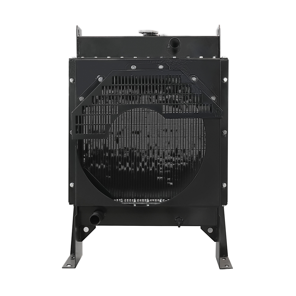
What Is a Heavy Duty Radiator and How Is It Different?
A heavy duty radiator moves far more heat than a light-duty unit, typically by increasing core thickness, fin density, and material gauge. While a passenger car radiator may be 16 mm thick and hold 2-3 liters of coolant, a heavy-duty version for a 400 HP diesel engine can exceed 50 mm core depth and circulate over 40 liters per minute. These differences are not incremental; they are structural.
The core face area, working pressure, and vibration tolerance all scale up. Heavy-duty cores are engineered for continuous operation at 90°C–105°C coolant temperatures under full load, often in contaminated air. They must survive high coolant pressures (15–18 psi standard, with high-performance caps reaching 25 psi) and thermal cycling that would crack weaker materials.
| Parameter | Light-Duty Radiator | Heavy-Duty Radiator |
|---|---|---|
| Core thickness | 16–26 mm | 32–70 mm |
| Material gauge (header/tube) | 0.3–0.4 mm | 0.5–0.8 mm |
| Operating pressure | 13–16 psi | 15–25 psi |
| Coolant volume | 2–6 liters | 10–40+ liters |
| Fin density (FPI) | 12–16 | 8–14 with louvered/dimpled fins |
| Mounting | Rubber-isolated | Rigid frame with vibration dampers |
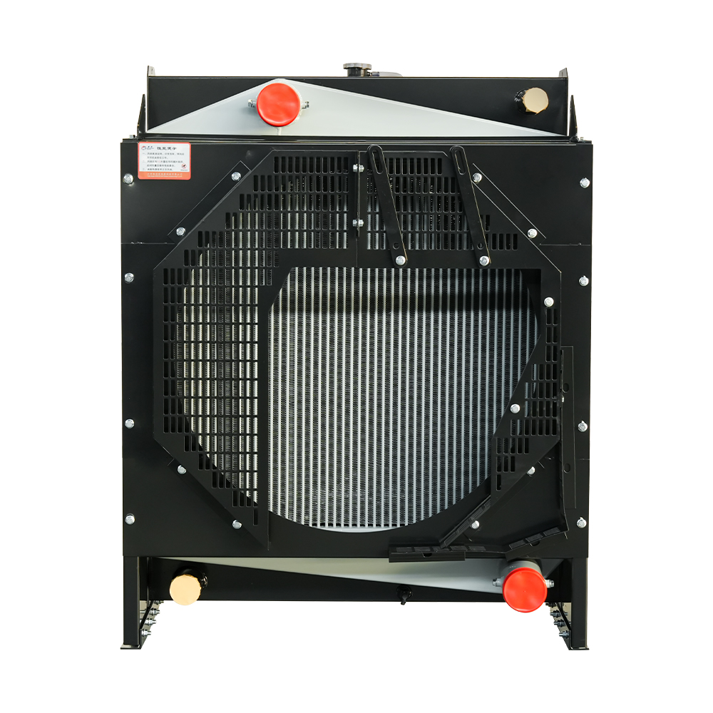
Aluminum vs. Plastic-Aluminum Radiators: Which Is Better for Heavy Duty?
Two primary material combinations dominate the heavy-duty aftermarket: all-aluminum (tanks and core) and plastic-aluminum (plastic tanks crimped onto an aluminum core). The choice isn’t about which is universally better — it’s about matching the material to the operating environment and maintenance philosophy.
All-aluminum radiators are brazed or welded into a single assembly. They eliminate the gasket/plastic interface that eventually weakens under heat cycling. Thermal conductivity is uniform, and the entire unit can be repaired by a skilled fabricator. In contrast, plastic-tank designs are lighter, cheaper to produce, and dominate OEM supply for over-the-road trucks. However, plastic tanks can crack if subjected to repeated engine flex, harsh chemicals, or high shock loads.
| Criteria | All-Aluminum Radiator | Plastic-Aluminum Radiator |
|---|---|---|
| Thermal conductivity | High, uniform | High (core), but plastic tanks insulate slightly |
| Corrosion resistance | Excellent with proper coolant; tanks won’t degrade | Aluminum core can corrode if electrolysis occurs; plastic resists external corrosion |
| Weight | Moderate to heavy | Lighter |
| Repairability | Welded repair possible; recoring feasible | Plastic tank replacement is limited; often replaced as unit |
| Typical lifespan | 8–15 years in severe service | 5–10 years; plastic tanks may need replacement after 5–7 years |
| Best suited for | Mining, construction, marine, stationary generators | Highway trucks, buses, fleets with planned replacement cycles |
When uptime is non-negotiable and the machine operates in high-vibration, high-temperature conditions, an all-aluminum radiator is the low-risk option. Fleets that replace radiators preventively often stick with plastic-aluminum to lower acquisition cost, but they must monitor tank-to-header seals closely.
Tube-and-Fin vs. Plate-and-Fin Core Designs: Pros and Cons
The core — the matrix of tubes and fins — determines how quickly heat moves from coolant to air. Two architectures dominate: tube-and-fin and plate-and-fin (also called bar-and-plate). Their behavior under shock, dust, and thermal load is radically different.
Tube-and-Fin (Serpentine Fin)
Oval or flat tubes carry coolant while thin fin strips run between them. This design is light and offers a large frontal area for air. It is the standard in on-highway trucks because it balances cost, weight, and cooling performance. However, the fins are easily deformed, and under severe vibration, tube-to-header joints can fatigue. Pressure capability is moderate — typically around 18–20 psi without reinforcement.
Plate-and-Fin (Bar-and-Plate)
Stacked plates create both coolant passages and air channels in a single rigid block. The structural integrity is significantly higher. This design withstands vibration and pressure spikes above 25 psi, making it suitable for mining and heavy industrial equipment. Heat transfer per unit volume can be 10–15% higher than tube-and-fin in dusty environments because the broader fin openings resist clogging. The trade-off is higher weight and cost.
For generator sets that experience constant vibration and limited airflow, a plate-and-fin generator radiator often outlasts tube-and-fin alternatives. When cleanability is a daily concern — such as in chaff-heavy agricultural applications — tube-and-fin designs with wider fin spacing still perform well and are easier to blow out.

How to Size a Heavy Duty Radiator for Your Engine
A common mistake is selecting a radiator based solely on vehicle fitment charts. Engine heat rejection dictates the core dimensions, not the available space. Start with the engine’s rated power and its brake-specific fuel consumption to estimate waste heat. A rough but dependable rule of thumb for turbocharged diesel engines: every horsepower rejects approximately 35–45 BTU/min as heat. The radiator must dissipate 60–75% of that total heat load, with the remainder handled by oil coolers and radiation from the engine itself.
Use this simplified formula to estimate core face area:
Core face area (sq in) = (Engine HP × 0.3) to (Engine HP × 0.5)
For a 400 HP engine, that yields 120–200 sq in of face area, which translates roughly to a 24" × 6" core to a 28" × 8" core, depending on thickness and air flow. However, face area alone isn’t enough. Core thickness (depth) and fin density must be considered together. A thicker core (50–70 mm) can compensate for a smaller face area but demands higher fan power and is harder to clean. Always verify that the radiator’s heat rejection rating under specified air-on and coolant-on temperatures meets or exceeds the engine’s manufacturer data sheet.
Coolant flow rate is equally critical. The radiator must be rated for the engine’s water pump flow at rated RPM. Exceeding the design flow velocity causes erosion; falling short creates hot spots. As a guideline, tube velocity should stay between 2–4 m/s for aluminum tubes. Pairing an engine with a high-flow pump to a surplus radiator can quickly lead to tube failures.
5 Common Heavy Duty Radiator Failures and Diagnostic Steps
Most cooling system emergencies give warnings long before total failure. Knowing what to look for turns a roadside breakdown into a scheduled maintenance event.
- Core blockage (external or internal). Symptoms: gradual temperature rise under load, uneven core surface temperature (cool spots). Causes: external dirt/debris between fins, internal scale from neglected coolant. Diagnostic: use an infrared thermometer across the core; temperature difference exceeding 15°C indicates flow restriction. Perform a back-flush and inspect fin cleanliness.
- Weld or tank seam cracking. Symptoms: visible coolant seepage, white residue at header/tank joint, sudden coolant loss. Causes: thermal fatigue, vibration, over-pressurization. Diagnostic: pressure test the system to 15–18 psi and look for leaks with a UV dye kit. A cracked seam often requires a full recore.
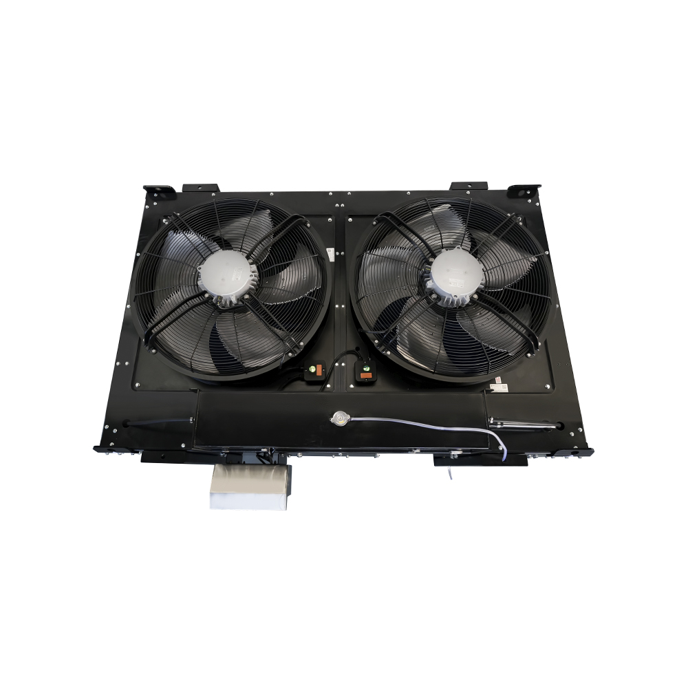
- Fan clutch or electric fan failure. Symptoms: overheating at idle or low speed, normal temperature at highway speed. Causes: worn viscous fluid, electrical fault in fan controller. Diagnostic: with engine off, check fan spin resistance; it should have noticeable drag when hot. Scan for fault codes in electronically controlled fans. A digital pyrometer can confirm air-on temperature at the radiator face.
- Radiator cap pressure loss. Symptoms: coolant boiling at normal gauge reading, collapsed hoses after cooldown. Causes: worn cap seal or spring, debris on sealing surface. Diagnostic: test the cap with a hand pump gauge; it should hold its rated pressure (typically 15–18 psi). Replace if it bleeds down faster than 1 psi per 10 seconds. A simple 2-minute test prevents more serious failures.
- Air pockets or system gassing. Symptoms: erratic gauge, gurgling sounds, localized overheating. Causes: trapped air after refill, combustion gas leak through head gasket. Diagnostic: use a combustion leak test kit on the radiator neck to detect exhaust gases. Bleed the system using the highest point or a vacuum fill tool. Persistent air indicates a head gasket issue, not a radiator problem.
Extreme Environment Considerations: Desert, Coastal, and Mining
Standard radiator specifications fall apart when ambient temperatures exceed 50°C, salt spray coats every surface, or airborne dust clogs fins within a shift. Environment drives both material selection and core architecture.
- Desert and high-ambient locations: Specify thicker cores (55–70 mm) and increase fin density only if dust load is manageable; otherwise, use a wider fin pitch (10–12 FPI) and increase face area. A fan with 10–15% higher airflow than standard is mandatory. Remote-mounted cooling packages with remote radiator layouts can move the heat rejection away from engine compartment heat soak.
- Coastal and offshore: Salt-laden air attacks aluminum brazing joints and accelerates electrolysis. All-aluminum construction with epoxy-coated headers and stainless steel side channels resists pitting. Brass/copper cores, though heavier, still find niche use where sacrificial corrosion is preferred, but modern heavy-duty designs rely on coated aluminum and proper coolant inhibitors.
- Mining and quarrying: Dust and vibration are the twin killers. Plate-and-fin cores survive where tube-and-fin designs crack. Extra header reinforcement and vibration-dampening mounts are not optional. In many pit operations, a mining-site generator radiator is designed with louvered guards and reversible fan logic to self-clean. Fin height below 6 mm helps debris shed naturally.
OEM vs. Aftermarket Heavy Duty Radiators: When to Choose Which
The decision between an OEM radiator and an aftermarket unit hinges on equipment age, warranty constraints, and performance requirements. OEM radiators are drop-in replacements that preserve factory warranty and meet baseline specs. Aftermarket options, particularly from specialized manufacturers, can exceed OEM performance through thicker cores or premium materials.
| Factor | OEM Radiator | Aftermarket Radiator |
|---|---|---|
| Cost | 30–60% higher | Base price lower; premium upgrades may match OEM cost |
| Warranty | Matched to equipment warranty | Varies (12–24 months typical) |
| Performance margin | Designed to minimum spec | Can be uprated with thicker core, all-aluminum, or better fan shroud |
| Availability | Lead times 2–8 weeks | Often in stock; custom orders in 2–3 weeks |
| Best for | Under-warranty equipment, leased fleets | Out-of-warranty machines, custom applications, severe-duty upgrades |
If your engine is still under manufacturer warranty, the safe path is OEM. Once the warranty expires, an aftermarket radiator that upgrades from plastic tanks to all-aluminum and increases core thickness can reduce operating temperatures by 3–5°C under full load — a margin that directly extends component life.
Maintenance Checklist to Extend Radiator Life
Cooling system neglect is the leading cause of avoidable engine failure in heavy equipment. Following a structured inspection routine prevents minor issues from cascading into core replacements.
| Task | Frequency | Tools needed | Time required |
|---|---|---|---|
| Check coolant level and color (visual) | Weekly | Flashlight | 2 min |
| Inspect hoses and clamps for seepage | Weekly | Inspection mirror | 3 min |
| Clean external fins with compressed air (blow from engine side outward) | Monthly | Compressed air, wand, safety goggles | 10–15 min |
| Pressure-test radiator cap | Quarterly | Hand pump tester | 5 min |
| Check fan belt tension and fan clutch engagement | Quarterly | Belt tension gauge, pyrometer | 10 min |
| Test coolant concentration and pH; flush if degraded | Annually | Refractometer, test strips, flush kit | 1–2 hours |
Airflow is everything. Even a thin layer of dust on fin surfaces can reduce heat transfer by 10–15%. Combined with a weak fan clutch, you’re already on the path to a roadside failure. Build these checks into your preventive maintenance software and track temperature trends month over month. A gradual increase of just 3–5°C on the digital gauge over six months is the first clue that a radiator is losing efficiency — and a call to inspect it before the season turns harsh.
- Product Categories
- Contact Us
-
- wcradiator@jswcsrq.com
- +86-514-400-180-4088
- +86-15152759383
- +86-15152759383
- No. 6 Road, Shaobo Industrial Concentration Zone, Jiangdu District, Yangzhou City, Jiangsu Province, China

